Raspberry Pi garage door controller
In this article I show how I use the raspberry pi to control a Tormatic GTA 620 garage door motor from a smartphone.
This is not meant to be a super detailed tutorial, but rather a short overview how I used a RPi to control the garage doors. If you have any questions, feel free to ask in the comments!
At my parents house there are two garage doors operated by a Tormatic GTA 620. The GTA 620 is controlled by a remote control. The task was to build a system for monitoring the garage doors status open/closed and to control the doors if needed.
The idea was to use a raspberry pi as a main controller in the garage. After some research on home automation frameworks I found pimatic to best fit my needs. It's a home automation system especially designed for the RPi, running on node.js.
Overview
The system works like this:
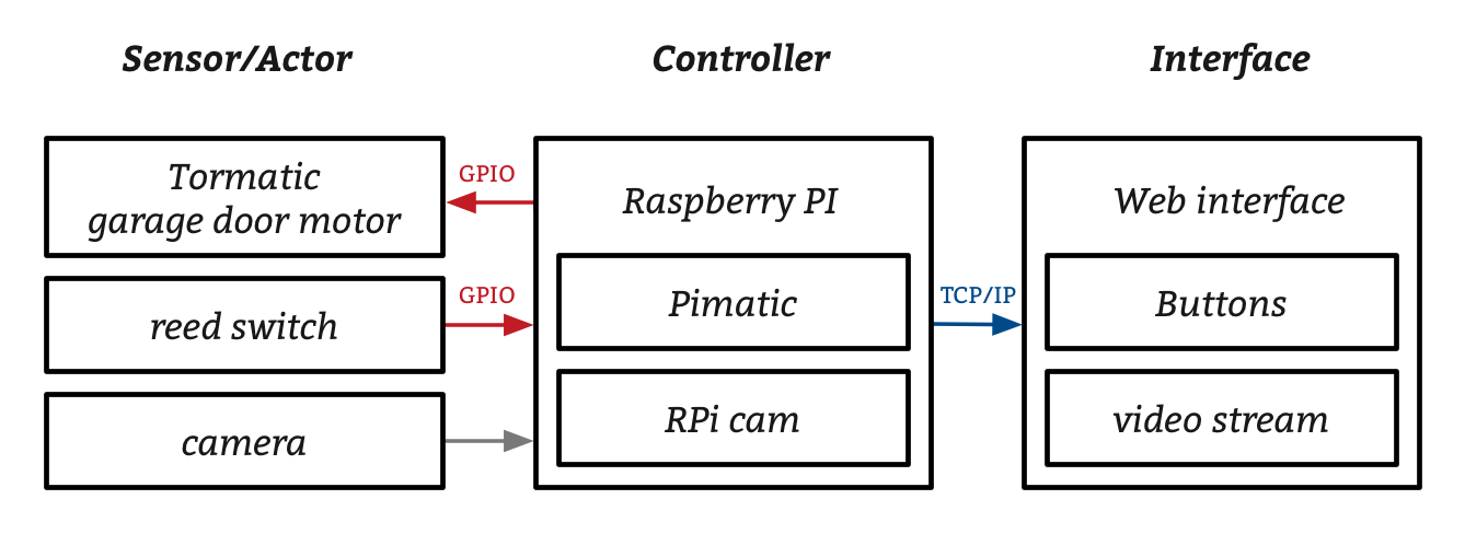
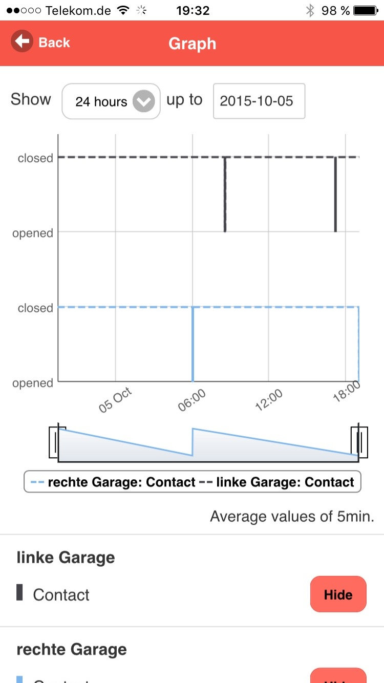
The main component of the system is the RPi. It runs all the necessary software and connects to both the sensors/actors and the internet. Reed switches in combination with magnets are used to monitor the doors state. They are attached to the RPis GPIO pins. The tormatics motor is also controlled by the RPi. A camera is connected to be able to check that nobody is in between the doors, when closing them remotely.
Hardware
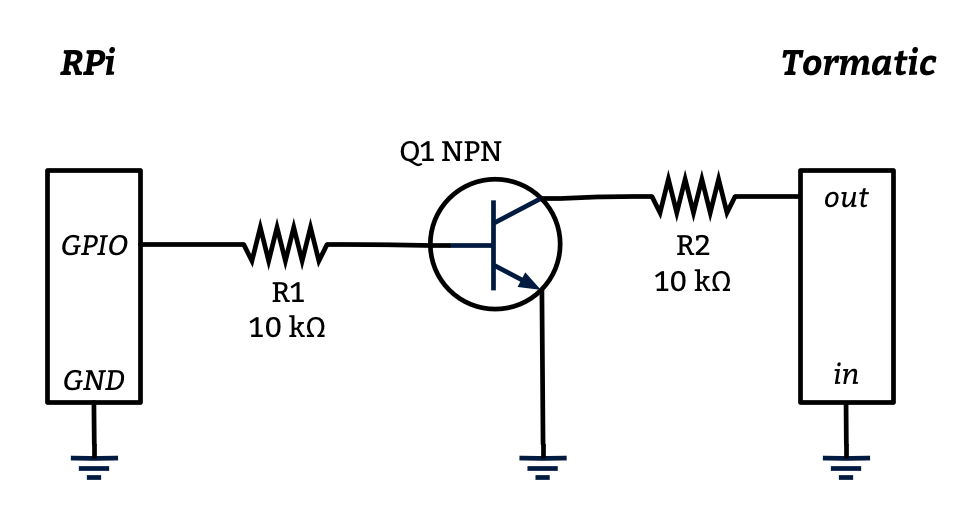
The tormatic garage door opener works by receiving a pulse from a remote or a physical switch. The pulse from a physical switch can be emulated using a simple transistor circuit and the RPi to switch it. A transistor was connected to the tormatics switch output and to the RPis GPIO pins. Some random resitors were added to the circuit for a more sophisticated look. If the GPIO is high (3V) the transistor is on and switches the garage door motor.
I assembled all the electronics in the FabLab of my university. Shout-out to the folks at FabLab. They helped me picking the right components and introduced me to their equipment. This template helped a lot to identify the right pin numbers on the RPi.


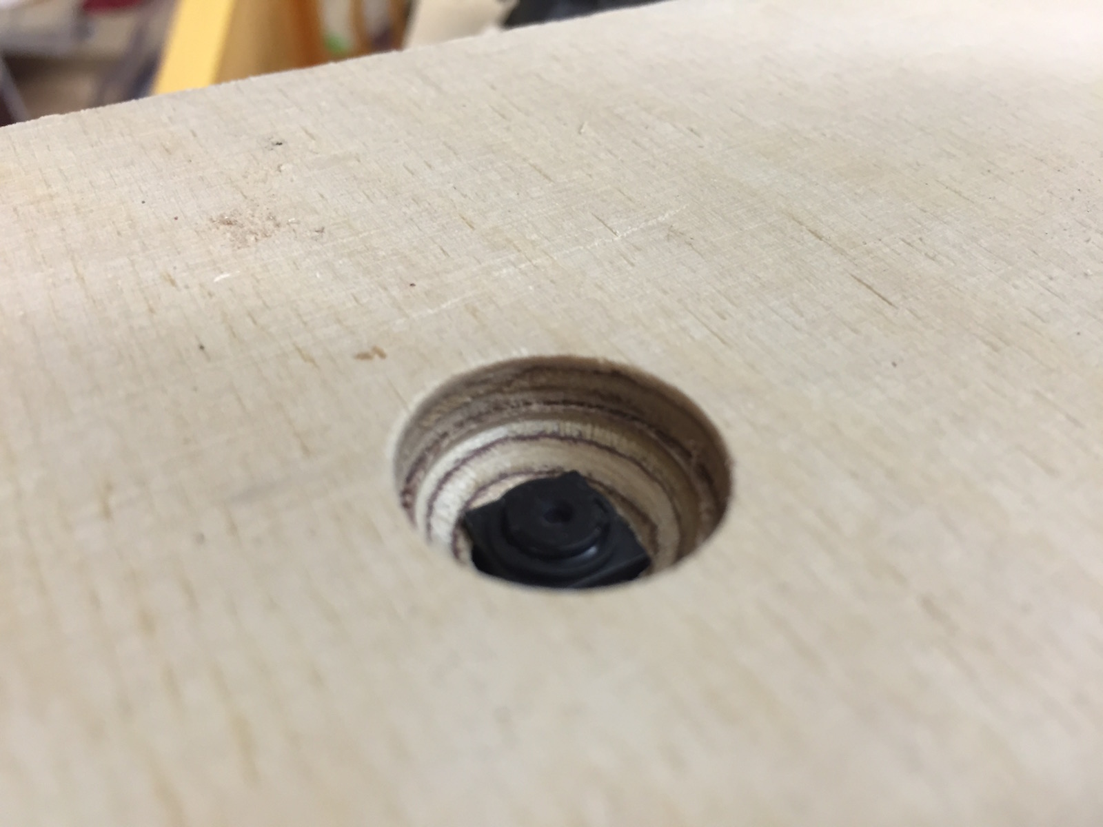
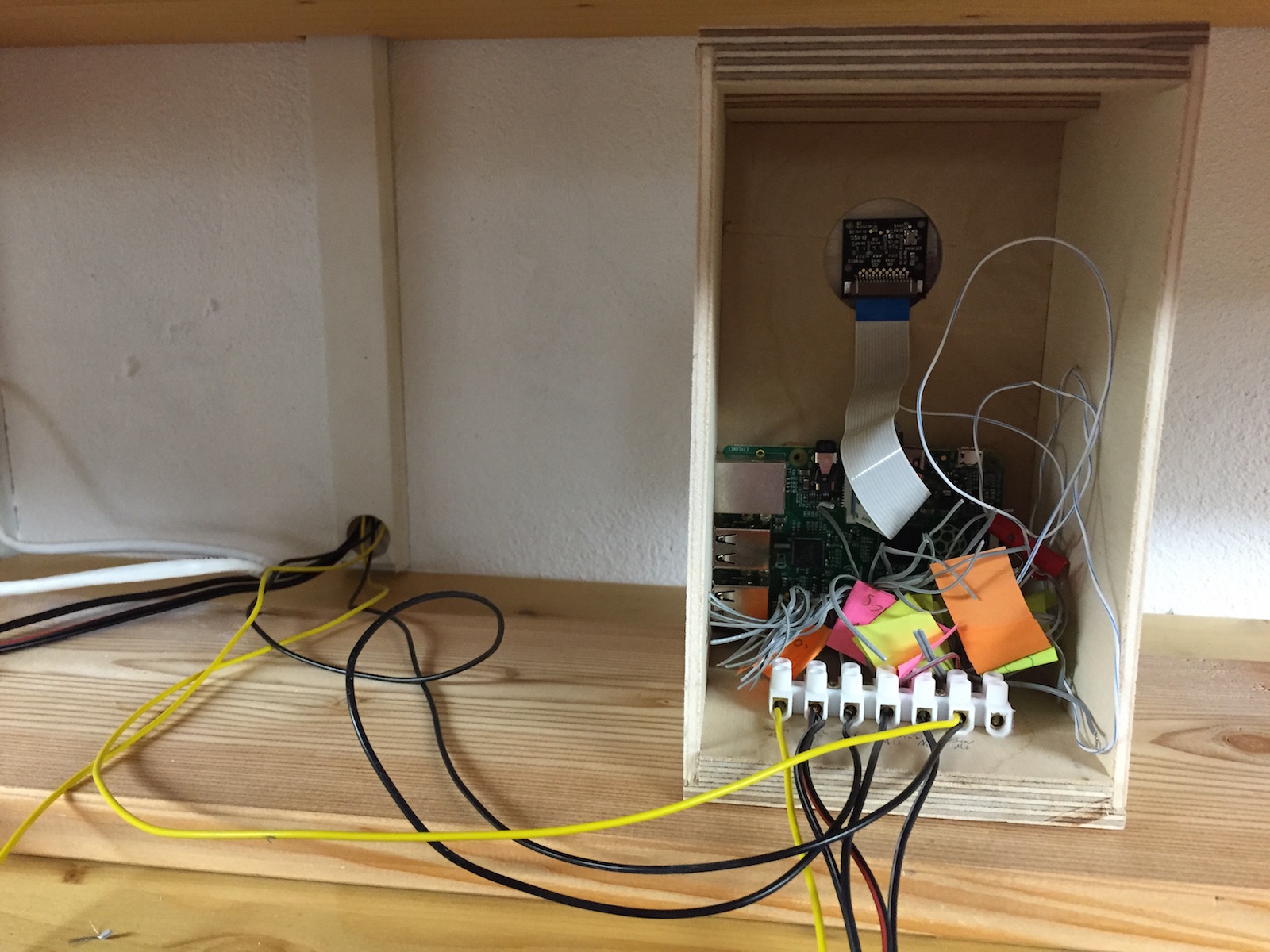
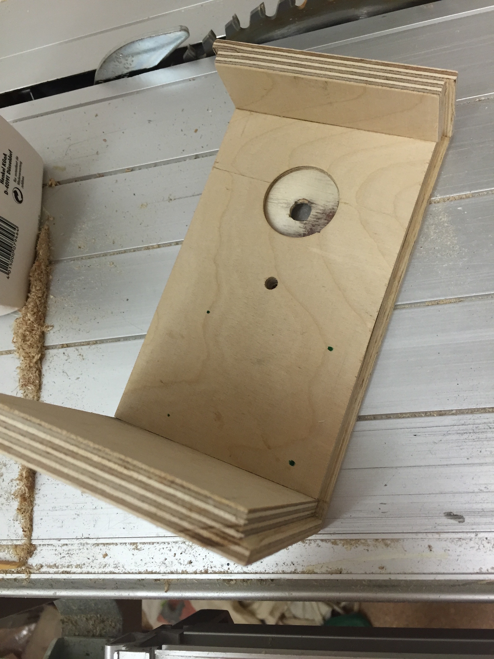
I made a small wooden box to protect RPi. I drilled two holes in the box. One for the camera and one for a small status LED. The LED is turned on by pimatic and therefore indicates, that the system is running. This is a useful feature when debugging, since there is no screen attached to the RPi.


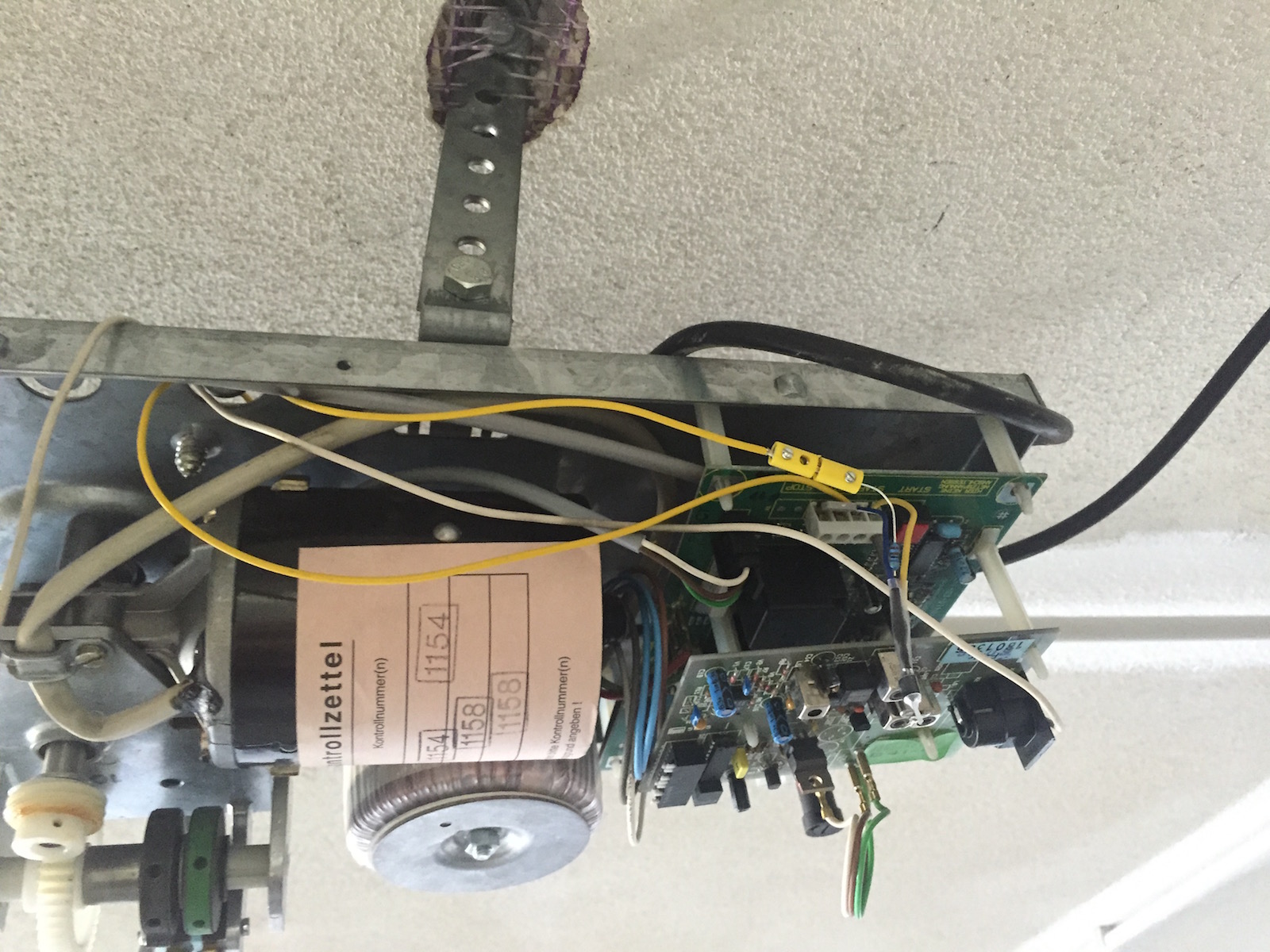

We mounted the wires to the ceiling using PCV tubes. The reed contacts were glued to the GTAs metal rails and secured with a metal wire, to prevent them from falling down and damaging the cars. The wires switching the Tormatics motor were fed in from a hole in the top plate of its case.
Software
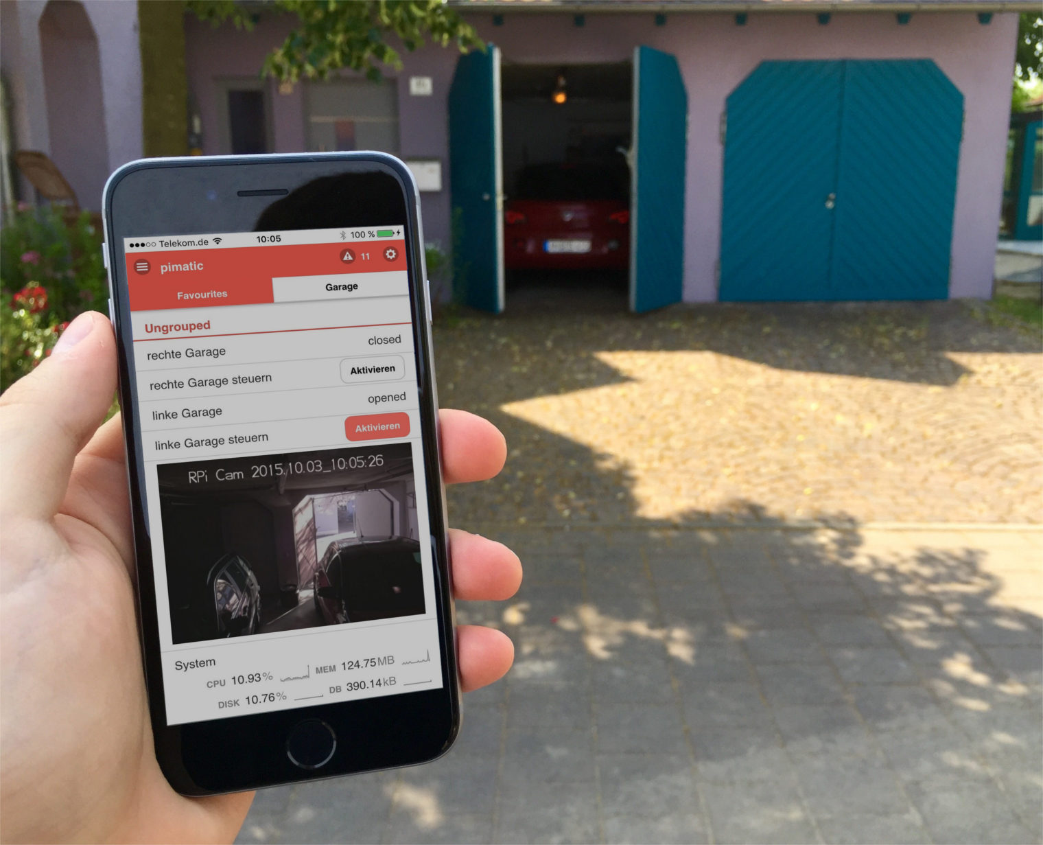
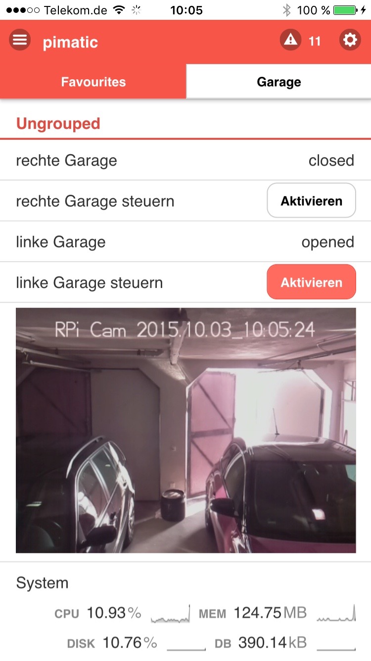
To be able to control the garage from a smartphone a webinterface is needed. Fortunately there is already a home automation framework called pimatic. It is specifically designed to run on a RPi. There were already modules to control and monitor the state of the RPIs GPIO pins. Setting it all up was just a matter of downloading and installing node and pimatic on the RPi. Pimatic can be configured via a json file. In this file modules are loaded and the GPIO Pins are mapped to different functionality (read/sensor, write/actor) Further information regarding Pimatic configuration can be fount in the official docs.
{
  "id": "contact-sensor",
  "class": "GpioContact",
  "name": "left garage",
  "gpio": 18
},
{
  "id": "left-garage",
  "class": "GpioSwitch",
  "name": "left garage",
  "gpio": 17
}
The video livestream system is based on the RPi-Cam-Web-Interface. A pimatic wrapper was used to embed the video (actually its a series of images loaded) in the webinterface. I set up a free DynDNS with my router to be able to access the control from everywhere.
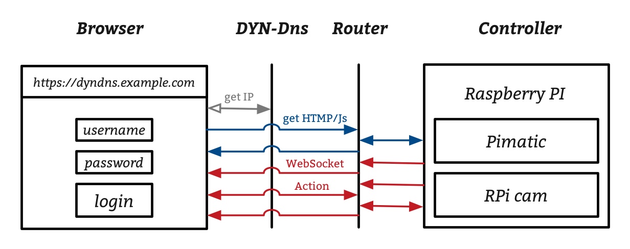
If I visit the dynDNS url in a webbrowser, the browser receives the current IP of my house connection (router). I added a port forwarding rule to the router to forward incoming traffic on port 5555 to the RPi in the garage. If a connection is established and access is granted, updates are pushed via websockets to the client.
The system works quite reliable for over a year. Next up is to find a way to integrate it with Apple HomeKit. There is is already a promising node.js library, which I'll try to implement into the system :)
← dice 8
→ Arduino as ISP to change the bootloader and burn sketches